
In one of my previous posts, I had written that during testing, I found the AT89C52’s oscillator to be unstable and unreliable at 11.0592 MHz. I had also found that the RESET signal going to the AT89C52 via the GAL22V10 was also “lingering” mid-rail before returning low, which was causing intermittent failures to reset the MCU. I have since then found and corrected both problems.
Reset: In my original design concept, I had two reset sources; 1) hardware reset switch and 2) the ICP connector. I fed these into the GAL22V10 so that I could use either one to reset the MCU. However, the GAL22V10 has no hysteresis in its inputs, so the output was lingering around mid-supply rail when the decaying input voltage from the manual reset circuit was between its Vih and Vil thresholds. This mid-rail lingering seemed to confuse the MCU and it would not reliably reset. As I posted earlier, I decided to set the GALS22V10’s output mode for the RESET signal to registered, which meant I need to feed it a clock signal. The only one I had available was from the XTAL2 pin of the AT89C52. After directly connecting the pins, I started to see the oscillator problems. I then inserted a buffer in between but that still did not cure the oscillator problem but the RESET signal no longer lingered mid-rail and that seemed to help.
Oscillator: After setting the GAL22V10’s output to register the RESET signal, the AT89C52’s oscillator was still unreliable. I thought it was the loading capacitors and tried larger values, which seemed to work better but there were still failures. When I switched to a 16 MHz crystal, I had no oscillator failures at all, which led me to believe that the 11.0592 MHz eBay crystals I ordered may have been rejects. However, I could not get the MCS-BASIC to emit a prompt, which led me to believe that I may need to update and reassemble the source code to run with a 16 MHz crystal. I knew that the 1.31 version was supposed to run with MCU’s up to 40 MHz, so it seemed rather unlikely that reassembly was necessary.
Realization and correction: The buffer I used between the AT89C52’s XTAL2 output and the GAL22V10’s CLK input was a FAIRCHILD NC7SP04 “Single inverting buffer”. It was housed in an SC-70 5-pin package. In testing, it seemed to properly buffer the XTAL2 output but in looking at the datasheet once more, I realized that it was only rated to work up to 3.6 volts, not the 5 volts I was using it at. Well, that could be a problem and MIGHT be causing some loading on the oscillator. I had also decided that I needed to add a Schmitt trigger buffer between the manual reset circuit and the GAL22V10 to add some hysteresis. Since I have them for another project, I used a FAIRCHILD NC7WZ17 “Dual buffer with Schmitt Trigger input”, which IS rated to 5.5 volts. Once again, this part was housed in an SC-70 package but with 6 pins instead of 5. Once wired in, I could see that the RESET signal had very clean rising and falling edges with no mid-rail lingering and that the GAL22V10’s CLK signal was also clean.
I was back to using the 11.0592 MHz crystal at this point and I tried to make the oscillator fail again with multiple sequential presses of the reset switch and I could not make it fail. The oscillator was now operating reliably as was the manual reset function, as was MCS-BASIC. Yippee! So it seems that the NC7SP04 was causing some oscillator loading. Technically, since I have added a Schmitt trigger buffer to the manual reset circuit, I no longer need to use the GAL22V10’s RESET output in registered mode. However, I do not have a single Schmitt trigger buffer, so for the time being, I’ll leave the AT89C52’s buffered XTAL2 output connected to the GAL22V10’s CLK input, otherwise I would have to run a ground wire to the unused Schmitt trigger buffer input.
I had recently received some 20 MHz crystals for this project. Now that the oscillator and reset circuits were stable, I decided to try one of those. The 20 MHz crystal performed flawlessly and MCS-BASIC ran fine at that higher frequency as well. MCS-BASIC still prints “11059200” when the “PRINT XTAL” command is issued, so apparently, it does not calculate its operating frequency, only the baud rate being used. I’ll figure out how to “hardwire” the proper frequency later.
Since I was now operating the AT89C52 at a higher crystal frequency, I checked the run current of the board and measured it as ~155 ma, which is only a few milliamps higher that it was when running at 11.0592 MHz.
Below is the modification that adds the FAIRCHILD NC7WZ17 to the bottom side of the PCB.


I still want to program the CAMEL-51 FORTH into the EEPROM and I need to finish testing the address decoding when switching between internal program memory and external program memory (EA=0 or EA=1). I’ll post more on that as I make progress but I’d like to switch back over to the Z80 SBC project for a bit since it has been neglected for over a month.
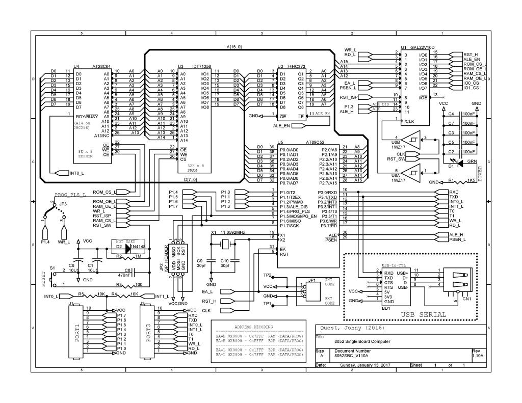
The current 8052 SBC schematic is shown below. A PDF version is here.
The AT89S52’s should be in by the 17th of January. Since I now have my MiniPro TL-866CS modified to be a TL-866A, the ICSP interface works and I should be able to use it to ISP program the AT89S52’s.
For those owning a TL-866CS programmer wishing to upgrade it to a TL-866A, here are links to the instructions. I used the files and step-by-step instructions in the first post of the first link and had no issues with the upgrade.
- https://atariage.com/forums/topic/246355-minipro-tl866-upgrade-instructions/
- http://blackstufflabs.com/2013/11/18/conversione-programmatore-tl866cs-a-tl866a/?lang=en
- http://www.eevblog.com/forum/blog/eevblog-411-minipro-tl866-universal-programmer-review/msg225443/#msg225443
- https://github.com/radiomanV/TL866
For those of you using Linux, there is an open-source command line utility for the TL-866A(CS) here:
Happy New Year and Peace and blessings.

One thought on “Oscillator functioning properly – All looks well”